1.1.1. LakiBeam
1.1.1.1. Mechanical Interface
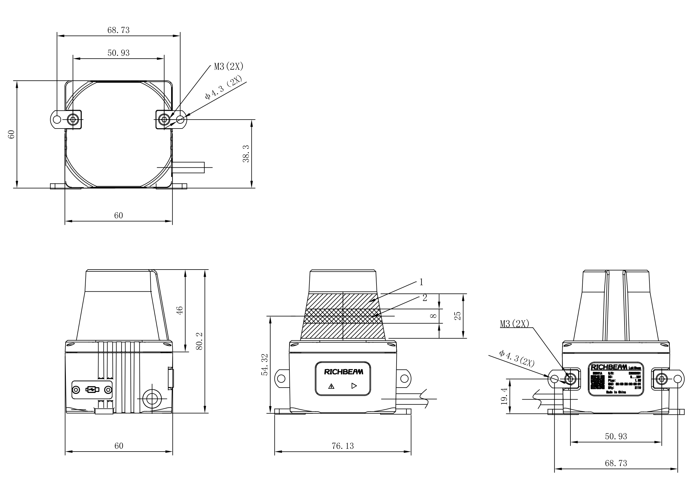
Please install the LakiBeam in the appropriate position according to the size and installation hole size shown in the figure below.
1.1.1.2. Coordinate Transformation
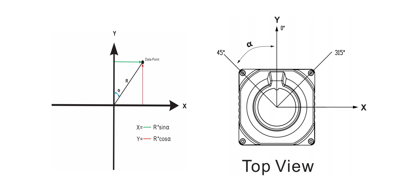
Since the radar’s MSOP packet only outputs horizontal rotation angle and ranging information, when converting it into a 2D point cloud, it is necessary to transform the polar coordinates (angle and distance) into Cartesian coordinates (x, y), as shown in the diagram below.
1.1.1.3. System Confirguration
In addition to USB connection, LakiBeam product family also provides a cable with RJ45 socket and DC 5.5-2.1 socket, users can use the cable to establish power and data connection with the product. Connect the RJ45 socket to the network through the Ethernet cable. To ensure connection stability, select Ethernet cables of CAT.5E or higher specifications. Connect the power supply to DC 5.5-2.1 socket.
1.1.1.3.1. Establish Connection
Network Cable Power Connection
LakiBeam product family has a built-in web server. When using this product for the first time, connect the network cable and power with the computer, the default network configuration of the product is static mode, and the factory settings of the product IP address is 192.168.198.2 (Device). Users need to manually change the IP address of the Ethernet port connecting the lidar to the computer to 192.168.198.1 (Host). Then users can access the web browser http://192.168.198.2 to the built-in web service of the product.
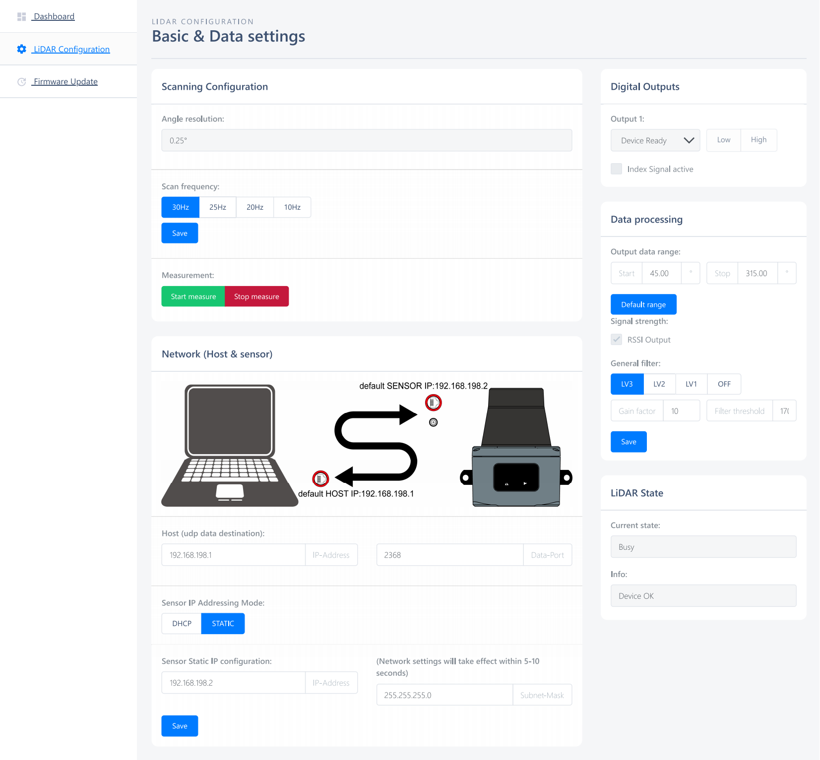
Note: Customers can modify the lidar IP address according to their needs, but they need to ensure that the lidar IP and computer IP are in the same network segment, and setting lidar IP address does not support 8 network segment.
For more detailed instructions on establishing a connection between lidar and computer, please refer to: LakiBeam Operation Tutorial.
USB Type-C connection
Windows/Linux Systems
Use a USB Type-C data cable to directly connect the device and the computer. Once the connection is established, the device requires approximately 30 seconds to complete the startup and self-check process. After the self-check is finished, the computer will recognize both a USB drive and a network adapter (RNDIS driver). The device creates a virtual network card on the user side, which is assigned a fixed IP address of 192.168.8.1 (Host side) through the device’s internal DHCP server, while the device itself is assigned a fixed IP address of 192.168.8.2 (Device side). At this point, you can access the device’s built-in web service by visiting {http://192.168.8.2} in your computer’s web browser.
macOS Systems
For macOS systems, an additional step is required: create a file named osx.apple in the root directory of the recognized USB drive. After safely ejecting the device and rebooting it, macOS will recognize a CDC-ECM device. Then, you can access the device’s built-in web service by visiting {http://192.168.8.2} in your computer’s web browser.
The built-in web service provides features such as a dashboard, radar settings, and firmware updates.
1.1.1.3.2. Download and Install RBView
Click on the official website link to enter the official website of Richbeam, where you can download the latest RBView and view the point cloud.
RBView currently supports Windows ® Version 10 and above.
Download the RBView file.
Double click on RBView Setupexe to start the installation, follow the prompts to complete the software installation.
Firewall settings
Since LakiBeam product family connects with the RBView through a network interface and continuously sends UDP data packets to a computer, the LakiBeam1(L) needs to penetrate a firewall of an operating system to obtain the data,so the firewall should be set up before use.
1 Open the Control Panel-> System and Security-> Allows an app through Windows Firewall
2 Click “Change Settings” to add the path of RBView.exe,which allows the RBView to communicate via the Windows firewall,click”OK”to complete the setup
3 ClickSelect the corresponding xml file of LakiBeam1 (L) in the Settings tab that pops up,and confirm that the settings of the Lidar IP and Host IP in the"Network configuration"are consistent with the lidar Web terminal setting, click"OK"
4 Clickicon view the point cloud data, and click the
icon again to pause
1.1.1.4. Data Interface
LakiBeam product family will send ranging data to the Host continously when starting measurement. The communication adopts Ethernet as the transmission medium, and the packet is based on UDP protocol. LakiBeam product family also supports HTTP-based RESTful(Representational State Transfer) interface that allow users to proactively request lidar data and set the current lidar status.
1.1.1.4.1. MSOP
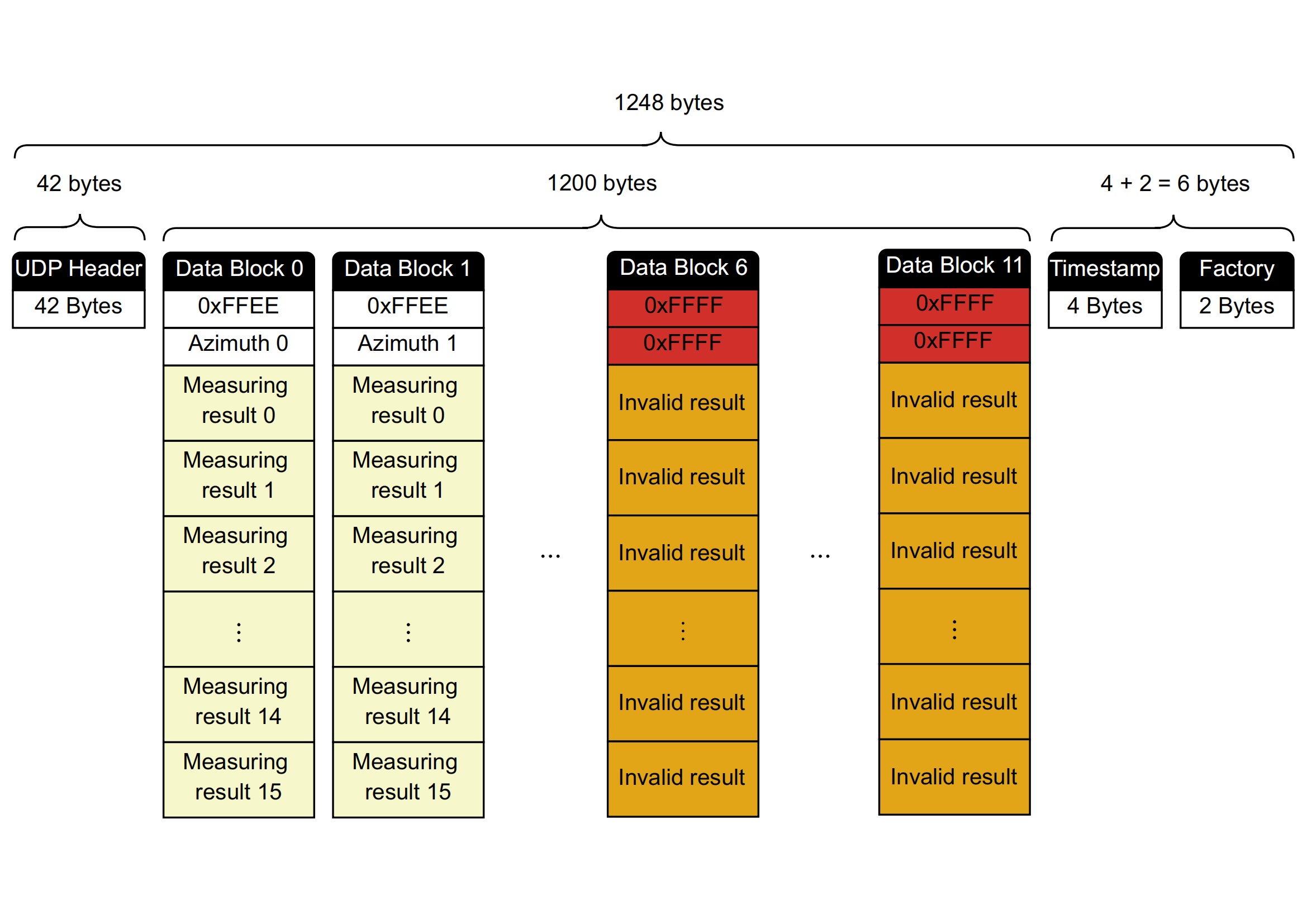
MSOP: Main data Stream Output Protocol. I/O type: device output data, computer parse data. Default port number is 2368. MSOP packet outputs data information of lidar ranging,each packet consists of measuring distance, RSSI, azimuth and a time stamp.Each MSOP packet payload is 1248 byte long and consists of a 42-byte UDP header,a 1200-byte data block (a total of 12 100-byte Data Block) and a 6-byte tail,each tail contains a 4-byte timestamp and a 2-byte factory information. The basic data structure of a MSOP packet is as shown in the figure below:
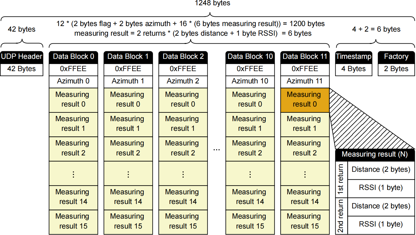
One of the things to note is that in the MSOP packets output on each turn of the lidar, the last MSOP packet is not exactly the same as the contents of the other MSOP packets. In the case of 20 Hz, 25 Hz and 30 Hz, when one turn of data (1440 sets of data at 20 Hz, 25 Hz and 30 Hz) is output, there are still 96 sets of data left in the last MSOP packet. That is, the data in the last 6 Data Blocks are not filled, so all data from Data Block 6 to Data Block 11 is invalid data, and the flag bit and Azimuth are 0xFFFF, and all invalid range data is also 0xFFFF, as shown in the figure below:
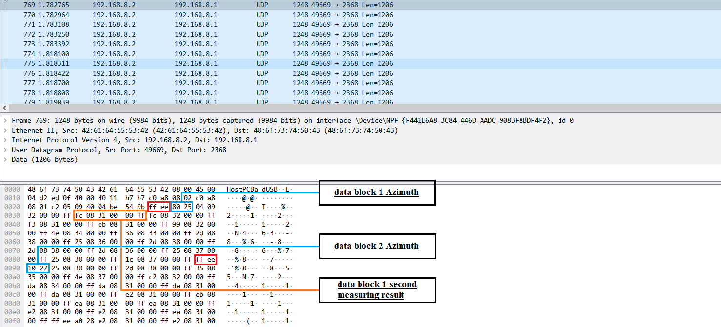
For example,in Figure 6.3, the azimuth of first Data Block in hexadecimal is: 0x80,0x25. Combine to a 16 bit, unsigned integer: 0x2580. Convert to decimal: 9600. Divided by 100, then get the result: 96.00 degrees. Hence, the horizontal angle of first Data Bloack is 96.00 degrees. Similarly, the azimuth of second Data Block in hexadecimal is: 0x10,0x27, then get the result: 100.00 degrees. Hence, the incremental value of the angle in Data Block is: (100 - 96) ÷ 16 = 0.25°. The ranging data and intensity of first Data Block in hexadecimal is: 0xFC,0x08,0x31,0x00,0x00,0xFF. The last three bytes are the last return data, if the ranging information in last return data is 0, that indicates no return data. Therefore the demonstration only parses data of stronget return. RSSI of stronget return is: 0x31, convert to decimal: 49.Hence, the RSSI of stronget return is 49. Then parse the distance of stronget return, combine to a 16 bit, unsigned integer: 0x08FC. Convert to decimal: 2300. Divided by 100 and convert to meter: 2.3m. azimuth:96.00 + 0.25 × 1 = 96.25. Hence, the second ranging data in first Data Block is: azimuth: 96.25°, distance: 2.3m, RSSI: 49.
1.1.1.4.2. RESTful API
LakiBeam product family supports HTTP-based RESTful(Representational State Transfer) interface. Users not only can connect to the lidar, view information, or modify settings through web server, but also can obtain the current lidar information or modify the current lidar settings through RESTful interface. The URL, HTTP verb, and HTTP status code of each specified resource of RESTful interface, see LakiBeam User Manual .